![]()
![]()
![]()
![]()
![]()
![]()
![]()
![]()
My URL: http://welcome.to/lokeang
![]()
An Introduction to ATM
Networks have become a common feature in the office environment, allowing access to e-mail and the internet, linking computers together and allowing several computers to access one printer. As more people want to be linked electronically, how are network technologies going to cope with the increased demand? This paper looks at Asynchronous Transfer Mode (ATM) as one possible solution to this problem.
| Introduction | Network Traffic | Packet-Switching Technology | Local Area Network | Wide Area Network | What is ATM? | ATM & OSI | Cell Structure | Quality | Switching | PNNI | LAN Emulation | Summary | Background Reading |
Introduction
As the requirement for information has increased, data communications networks have grown. Organisations can no longer function without using complex and diverse networks. E-mail, resource sharing and instant access to information have become normal working practices. To meet these requirements, a wide range of transmission lines, switches and multiplexers have been linked together to provide electronic connections between departments, offices, and buildings, separated by a few metres or many miles.
Asynchronous Transfer Mode technology is seen by some to be the solution to this ever-increasing demand for faster information transfer. It has the potential to replace many conflicting technologies and to form a single network that will use the same protocols over both short distances (local area networks (LAN)) and long distances (wide area networks (WAN)), for all types of information: voice, video, data and multimedia etc.
Before discussing ATM, it would be useful to give a brief overview of some of the types of traffic and network technologies currently used to communicate.
Network Traffic
At present there are three common types of network: telephone (POTS) for voice transmission, cable / satellite television for video transmission and packet switching networks for data transmission. There is very little overlap between the types of information. All are moving from analogue to digital technology and eventually, they may all merge into a single technology such as ATM.
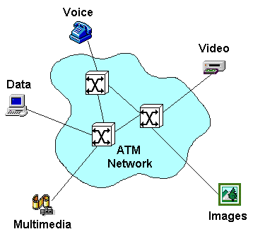
Figure 1: Different Types of Network Traffic
Figure 1 illustrates different types of information accessing a network. There are different requirements for each type of information.
Voice:
In its digital form, voice communication comprises of a continuous stream of bits, grouped together to form packets. It has a constant bandwidth of 65kbps required for the entire duration of the call. Voice communication is isochronous, i.e. it is very sensitive to timing. The bits have to arrive at the receiver at exactly the same rate as they are transmitted. If they are received slower than transmitted, there will be a build up of packets and some will be discarded by the network. If they are received faster than transmitted, the receiver will run out of packets and there will be gaps in the conversation. Voice transmission is also sensitive to transit delay i.e. the time taken to traverse the network. A delay of greater than 50ms is noticed as a gap at the change over of speaker. Voice transmission is tolerant to minor errors. Each packet only provides a small part of the word and there is enough redundancy in speech that the conversation will still be understood if the occasional syllable is missing. It is not feasible to re-transmit a missing or corrupted packet because it would arrive too late.
Video:
Video data consists of a series of still pictures or frames displayed at a rate of 25-30 per second. Video signals usually contain a lot of redundancy since only a part of the picture changes from one frame to the next. The bandwidth required is variable, depending on the quality of the picture and the amount of compression used. Video transmission is sensitive to timing. It is not so sensitive to transit delay but is affected by jitter, i.e. variations in the transit time. Video conferencing is sensitive to transit delay, because transmission is in both directions. Uncompressed video containing redundancy is more tolerant of small errors. Retransmission of corrupted packets is not feasible. Video transmission requires the audio and video signals to be synchronised to within 120ms.
Data:
Data is `bursty' in nature, i.e. there are periods when there is little or no traffic and periods when the link is saturated. This results in a very variable bandwidth which is difficult to predict. Data transmission is not timing sensitive or isochronous. It doesn't even matter if the packets arrive out of order. It is not affected by transit delay, but it is very sensitive to errors and so corrupted or missing packets must be resent.
Image:
Transmission of images is very similar to data, except that there is a very large amount data per picture and so a higher bandwidth is required.
Multimedia:
Multimedia can be a combination of any of the above, depending on the application. It is usually very information intensive requiring a large bandwidth.
Network Types
Telephone
Plain Old Telephone Service (POTS) uses circuit switching techniques to connect users. The callers are physically connected and have a fixed bandwidth for the entire duration of the call. This type of network is ideal for normal telephone calls because the bandwidth required is low and it needs to remain for the whole call. There has to be a fixed and minimal delay in transmission with little loss of data.
There are two types of POTS connections available: leased-line and dial-up. A leased line is a permanent, dedicated connection between two users. A dial-up connection requires the connection to be made before the call can take place and it exists only for the duration of the call.
Circuit Switching Technology
Communications over a public telecommunications network uses a point-to-point approach, physically connecting the two users together, as shown in figure 2. Switches and multiplexers interconnect the communications circuits allowing many users to share the network. Access to the network is achieved by simply plugging the computer, through a modem, to the telephone line.
This type of connection has a fixed bandwidth for the entire duration of the call. This is required for speech, which is time sensitive, but it is inefficient for data transmission because nothing else can use the bandwidth during the idle times between data bursts.
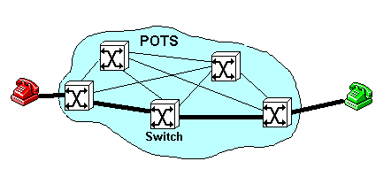
Figure 2: Circuit Switching Network
Computer Network Packet-Switching Technology
Another type of network technology is called packet-switching technology (figure 3). In contrast to circuit-switching technology where a fixed line is established between the two parties, packet-switching technology simply splits the data into packets, adds an address onto each packet and sends it onto the network. Routers in the network examine the address and pass the packet on in the right direction, towards the destination. The destination system intercepts packets that are addressed to it. Each packet between two users may take a different route and take a different length of time to make the journey. This results in variable delays and packets arriving out of sequence.
Packet switching technology is better than circuit switching for transmitting data because data is `bursty' in nature (i.e. there are periods when there is little or no traffic and periods when the link is saturated) and a fixed bandwidth is not required. It is also not time-critical and so it doesn't matter what route the packets take. By not tying up the bandwidth, other services can transmit data at the same time. It is not suited to speech and video because these forms of communication are sensitive to variable delays in the arrival of packets.
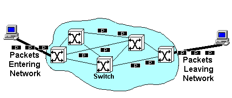
Figure 3: Packet Switching Network
Local Area Network
A local area network (LAN) is a network that allows devices such as personal computers, workstations, printers etc. to be connected together within a small geographical area. A LAN implements a multi-access data link, which means that more than two systems can be connected at the same time. It is used to transfer data in a fast and flexible way. It provides a simple data path along which any terminal connected to the LAN can transmit data to any other terminal on the network. Figure 4 shows different LAN topologies.
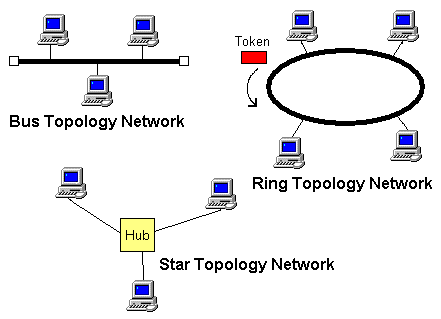
Figure 4: Different LAN Topologies
Several different technologies are available to transmit and receive packets of data:
- ethernet - terminals are connected to a common bus or tree of
coaxial cable or twisted-pair cable. Each terminal tries to transmit
whenever it has data to send.
Each terminal listens to the network and when there is no other traffic, it sends its data. This can result in a collision of data if two terminals are listening and decide to send at exactly the same time. If a collision occurs, each terminal waits for a different amount of time before trying to send again.
If the network is very busy, there are more collisions, resulting in more re-sends, making the network even busier. Eventually the network will grind to a halt. - token ring - terminals are connected to one another using
twisted-pair cable to form a ring.
A terminal is only allowed to transmit when it has the token, i.e. a special data unit. The token is passed from one terminal to the next around the ring.
Data passes around the ring in one direction, visiting each terminal. Each terminal examines the data and passes it on. If the data is addressed to it, it makes a copy before passing the it on. When the data returns to the sending terminal, it removes the data from the ring and sends the token to the next terminal.
Only data from one terminal can be out on the network at a time. This eliminates collisions, but makes the network slower if there is little traffic, since the sending terminal has to wait for the token to arrive. - token bus - terminals are connected to a bus or tree in a similar way to an ethernet. A terminal is only allowed to transmit when it has the token, which is passed from one terminal to the next in sequence in the same way as the token ring.
- Arcnet - a low speed LAN technology in which all terminals are connected to a common coaxial cable. A terminal transmits when it has the token in a similar way to token ring.
- Fibre Distributed Data Interface (FDDI) - a high speed LAN technology using optical fibre to connect the terminals in a ring. A terminal transmits when it has the token in a similar way to token ring.
- Local talk - a low speed LAN technology which is part of Apple Computer's AppleTalk.
- Wireless LAN technologies - e.g. radio and infrared.
Wide Area Network
A wide area network (WAN) is used to transfer data over a large distance usually using a point-to-point connection-orientated link. Some technologies used include:
- Analogue telecommunications - employ modems at each end to convert digital data to an analogue signal and vice versa
- Digital telecommunications
- X25 packet switched data networks - a packet-switched public data network (PSDN) uses packets that are routed individually through the network. X25 implements virtual circuits which appear as point-to-point links between users. Data rates are at about 64 Kbps
- Integrated services digital network (ISDN) - a public telecommunications network supplying digital end-to-end data transmission services which can be used to transmit any type of information, with data rates ranging from 64 Kbps to 1.92 Mbps.
- Broadband ISDN (B-ISDN) - a probable future technology based on optical fibres. It is designed to provide higher bit rates than ISDN, in the range of hundreds of megabits per second.
- Frame Relay - based on international standards for the data link and physical layers of the OSI reference model. Frame relay offers data rates of up to 2 Mbps and higher in some cases.
- Switched multi-megabit data service (SMDS) - high speed data transmission technology to carry WAN data at LAN speeds of between 4 and 34 Mbps.
- Wireless WAN technologies
Enterprise Network
An enterprise network is a form of integrated networking that links large wide area networks constructed by information systems organisations to local area networks created by users in individual workgroups.
One of the characteristics of networking is the diversity of equipment used to implement the network. Each subnetwork may use different technology, but they all need to interoperate if they are to work as an enterprise network.
OSI Reference Model
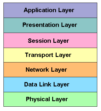
Figure 5: The OSI Reference Model
To facilitate interoperability of subnetworks within an enterprise network, ISO developed a reference model for open systems interconnection, called the OSI reference model shown in figure 5. It's purpose was to provide a common basis for the co-ordination of standards development for the purpose of interconnecting open systems. Open systems are systems which are open to one another by virtue of their mutual use of applicable standards.
The OSI reference model defines seven functional layers which are incorporated into each communicating machine. Each layer performs a different task, providing a service to the layer above. The way in which it performs its task is transparent to the other layers.
Physical layer
The physical layer is the lowest layer in the OSI reference model. It deals with the actual transmission of a bit stream in the form of electrical, optical or radio signals, across a physical circuit between communicating machines.
The physical layer refers to the permanent hardware installed in the communicating devices and the cables, connectors, modems etc. used in the physical network.
Data Link Layer
This layer deals with the transmission of data units, or frames, between adjacent nodes in a network. It also handles the grouping of data into frames and synchronisation with respect to failures in the physical layer. It covers error detection and recovery mechanisms for transmission errors, flow control and frame sequencing.
The data link layer refers to protocols such as ethernet and token ring for LAN's and ISDN, Frame Relay and ATM for WAN's.
Network Layer
This layer handles the routing decisions and relaying of data packets from endpoint to endpoint through the network, regardless of how many intermediate data links need to be traversed.
The IP part of TCP/IP is part of the network layer.
Transport Layer
The transport layer is interested in end-to-end integrity controls to recover lost, out of sequence or duplicate packets. This and higher levels are only present in end systems. They are not required in intermediate switches.
The TCP part of TCP/IP is in the transport layer. Other protocols represented by the network and transport layers include NetWare’s IPX/SPX and AppleTalk.
Session Layer
The session layer and layers above it are associated with application programs as opposed to the network itself.
The session layer organises the dialogue between the 2 application programs in the end systems and it manages the data exchanges between them. It establishes synchronisation points in the dialogue, so that the dialogue can be interrupted and resumed from a synchronisation point.
Presentation Layer
This layer preserves the information content of the data transmitted over a network. It enables two systems to exchange information without being aware of the specific data formats each system uses. This means that each system can use own preferred format.
Application Layer
The top layer of the OSI reference model deals with user processes. It is concerned with high level functions providing support to application programs using the network for communication. It provides the means for application programs to access system interconnection facilities to exchange information.
The top three layers represent services such as printing, file services, e-mail, directory services, network management, ftp, telnet etc. It covers the software used to make the network transparent to the end user.
What is ATM?
ATM or Asynchronous Transfer Mode was originally designed to carry broadband ISDN for digital communications, but also offers a way to integrate all types of data transmission into the same architecture.
ATM supports:
- The creation of a wide-area digital network which is not tied to a specific physical implementations, has flexible speed and is independent of the type of data it carries. It can incorporate optical fibre and wireless seamlessly alongside traditional copper-based connections.
- The provision of data transfer architecture which is scalable as improved physical resources become available.
- Connections of different bit rates depending on the application and physical connection used.
- Integration of wide area and local area networks using a common technology.
- On the business side, the ability to account for every unit of data delivered for identification and billing.
- Provision of a guaranteed quality of service to the end-user.
ATM protocols are standards-based, with co-ordination of ATM standards being performed by the ATM Forum. The ATM Forum is "an international non-profit organisation formed with the objective of accelerating the use of ATM products and services through a rapid convergence of interoperability specifications". There are many companies involved with the ATM Forum including Motorola, Microsoft, Nokia, AT&T, Mitsubishi, Ericsson, Sun Microsystems etc. A full list of members is available on their web page, http://www.atmforum.com/atmforum.
ATM is a connection orientated technology, using a small, fixed size cell of 53 bytes, allowing very rapid switching through the network. Before data can flow between two nodes on an ATM network, a virtual path is set up between them. Virtual paths as shown in figure 6, are like pipes between switches within the network. Each pipe contains one or more virtual channels, each of which carries an individual data stream in one direction only. To set up a telephone call, for example, a virtual path is required with 2 virtual channels of 64kbps each, one for each direction. Each virtual channel has its own bandwidth and service requirements.

Figure 6: Virtual Paths and Virtual Channels
Virtual paths are used because ATM is very fast and so very fast switching is required and conventional routers aren't fast enough. There isn't time to read a packet into a buffer, check it's destination address, consult a look-up table to find out where to send the packet to next and then send the packet out. ATM programs the switches with the identification number of the virtual path (VPI) and virtual channel (VCI) before data transfer begins. The cell contains only the short VPI and VCI (a total of 28 bits), not the entire destination address and the VPI and VCI are read and processed very quickly while the cell is still coming into the switch, so that the cell spends very little time at the switch itself.
Another advantage of using virtual paths and virtual channels is that once created, the path is fixed, barring equipment failure, therefore there is no risk of the cells getting out of sequence. This makes isochronous (time dependent) traffic easier to deal with.
During the path set up, a Quality of Service is also agreed. This addresses the bandwidth, transit time and jitter required by the traffic to be transmitted, allowing the ATM network to cope with the different types of traffic and guaranteeing the expected quality of connection to the end user.
ATM and the OSI Model
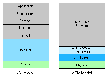
Figure 7: ATM Architecture Relationship to the OSI Model
ATM sits within the Data Link layer as shown in Figure 7. The ATM software is set up by a network software system implementing a transport protocol family, e.g. TCP/IP, IPX/SPX. The software is responsible for performing higher-layer functions associated with network processing.
Many of the functions normally associated with the network layer, e.g. addressing, routing, relaying are also performed in the ATM layer. Endpoints use the whole ATM model, whilst switches only use the physical and ATM layers.
ATM Cell Structure
Figure 8 shows a diagram of an ATM cell. In contrast to LAN packets which can have a variable length, an ATM cell is of fixed length. Every cell is 53 bytes: the first 5 bytes making up the header and the remaining 48 bytes for user data or additional control data, such as the ATM Adaption Layer (AAL) service. Short, fixed length cells cause shorter delays and less jitter (variance in the delay) than longer or variable length cells, making it more suitable for voice and video services. The cell size is fixed to simplify the switch design by minimising the overhead required to process each cell.
It is possible that cells will get lost. The switches only have small buffers and if there is a build up of cells at a switch, the buffer quickly overflows and cells are discarded. There is no error checking mechanisms for the user data at the data link layer. It is up to the higher level protocols to check for corrupted or missing cells. Unfortunately, the higher level protocols examine frames consisting of several cells and so if the quality of service requires re-transmission, the whole frame will be retransmitted even if only a single cell was missing or corrupted.
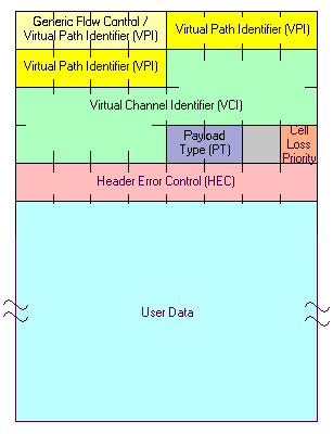
Figure 8: ATM Cell Structure
The Header
There are two types of cell header: the user node interface (UNI) and the network node interface (NNI) (see figure 9). The UNI establishes calls and connects applications to the network and the NNI deals with two separate ATM networks communicating with each other. The private network node interface (PNNI) is the standard for interfacing the ATM switches of different vendors. The structure of the header is given below:
Generic Flow Control (GFC), 4 bits
This field is only used in the UNI. It is intended to be used to define a simple multiplexing scheme.
Virtual Path Identifier (VPI), 8 or 12 bits
This field is 8 bits in the UNI and 12 bits in the NNI. It is used to group virtual channels into paths for routing purposes.
Virtual Channel Identifier (VCI), 16 bits
This field identifies a particular channel within a virtual path.
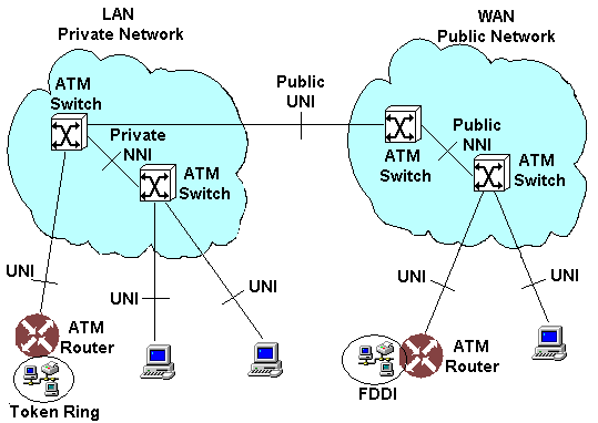
Figure 9: ATM Network Showing User-Network Interface (UNI) and Network-Network Interface (NNI)
Payload Type (PT), 2 bits
This field identifies the type of information in the user data field.
Cell Loss Priority (CLP), 1 bit
This field is used to determine which cells can be discarded first when congestion occurs.
Header Error Check (HEC), 8 bits
This field contains an error detection and correction code used to correct single errors and detect double errors in the header of the cell. This prevents cells being delivered to the wrong end user.
The User Data or Payload, 48 bits
The payload of an ATM cell can be of any sort, as long as it can be encoded digitally. The delivery mechanism is independent of the type of data to be delivered. The circuit itself doesn't need to know what is in the cells, just where to get them and where to put them.
Quality of Service
The ATM network defines Quality of Service (QoS) parameters based on the speed, accuracy and dependability required by the cells being delivered. There are different Quality of Service parameters because different types of information have different criteria, for example some data may tolerate delay but not loss of cells in the transfer process whereas other information e.g. real time video cannot tolerate delayed cells but accepts a certain amount of error or lost cells.
The Quality of Service is negotiated by the network before a connection is set up. Once configured, the network will guarantee to give the agreed Quality of Service to the end user.
The three most important parameters negotiated during the set-up of an ATM connection are:
Peak Cell Rate (PCR)
This parameter determines the maximum rate at any moment at which cells can be delivered across the circuit. If the rate increases beyond the PCR, the cells may be dropped along the way.
Sustained Cell Rate (SCR)
This parameter defines the continuous average rate that cells are available to pass through a circuit.
Minimum Bit Rate (MBR)
This parameter indicates the minimal amount of bandwidth that has been reserved for the circuit. If the source has nothing to deliver to the destination, empty cells will be sent instead to maintain the bandwidth.
The parameters are used to define the following ATM Classes:
Constant Bit Rate (CBR)
This class provides a continuous isochronous stream of data traffic transmission of video of broadcast quality, and voice. This should give performance equivalent to comparable private lines. It is an expensive option since the bandwidth is guaranteed between two points even if the line is idle. When there is no data to send, the link will send idle or blank cells at the same rate, effectively still using bandwidth when it isn't necessary.
Real-Time Variable Bit Rate (rt-VBR) and Non-Real-Time Variable Bit Rate (nrt-VBR)
These services allow data to be delivered in bursts. Video conferencing is an example of an application using VBR. There is enough redundancy in the video signal that the loss of one frame won’t noticeably affect the output. rt-VBR is more concerned with controlling the transit delay between the sender and receiver than nrt-VBR.
Unspecified bit rate (UBR)
Internet access uses UBR. This service does not specify the transit delay and it doesn’t care if the cells are successfully delivered to the receiver or not. It leaves these things to higher level protocols, such as the Internet Protocol (IP).
Available Bit Rate (ABR)
This is similar to UBR in that it can vary the transmission rate of cells at any time, but it offers better quality of service guarantees.
ATM Adaption Layer (AAL)
The ATM adaption layer is the service that converts a particular data source into a particular type of ATM traffic, i.e. it handles the mechanics of setting up the quality of service required by the user. There are 4 classes defined:
- AAL1: constant bit rate data with time dependence
- AAL2: variable bit rate data with time dependence
- AAL3: variable bit rate data which is time independent
assured operation - error recovery
non-assured operation - error recovery left to higher levels. Flow control optional - AAL4: connectionless service
There are 2 layers within the AAL:
The convergence sublayer
This layer inserts a header and trailer around the user's data, defining the service required.
The segmentation and reassembly layer
This layer receives the data unit from the convergence sublayer and divides it into pieces for transmission. It adds a header with re-assembly instructions.
Switching
A key process in ATM is the switching devices which process the cells at extremely high bit rates.
Simple switches are required to enable the high speed required by ATM. The cells are small and fixed in length (53 bytes) to optimise the switching architecture. The connection oriented nature of ATM enables the switching elements to have pre-defined routing tables to minimise the complexity of single switch routing. An ATM switch typically handles several hundred thousand cells per second at each switch port. A single switch may have thousands of ports.
In the simplest switch design, such as the one shown in figure 10, there are a number of links to transmit and receive cells. Cells are received by the switch and re-transmitted on the corresponding outbound link according to routing table within the switch.
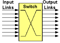
Figure 10: A Simple Switch
The core of the switching process is as follows:
- A cell is received on an inward link and its header is examined to determine the outward link.
- The VPI/VCI fields are changed to new values appropriate to the outward link and a new HEC (Header Error Checker) value is calculated.
- The cell is re-transmitted towards its destination on the outward link.
- During this process the sequence of the cells is preserved through the switch.
There are many other tasks that a switching node must also perform:
- The Header Error Check (HEC) field must be checked on all incoming cells. If an error is found, the cell is discarded to prevent the mis-routing of cells. When a cell is transmitted with new VPI and VCI values, the HEC field must be re-calculated and inserted into the cell.
- There must be a mechanism for handling congestion within the switch. This often takes the form of discarding cells when congestion occurs.
- There must be a control mechanism for updating VPI/VCI routing tables within the switch.
- There must be an Operations Administration and Maintenance (OA&M) system for set-up, operation, and control of the network and for fault diagnosis and reporting.
- There must be a system for collecting billing information.
Crosspoint Switch
Crosspoint switches (figure 11) operate by a circuit switching technique. The inputs and outputs are connected to a number of separate parallel data paths. The input paths are at right angles to the output paths to form of a matrix. At each intersection of input and output paths (crosspoint) there is a switch. Any input can be connected to any output simply by turning on the appropriate switch. Only one input may be connected to any one output at a time, but (potentially) a single input could be connected to multiple outputs. For this type of switch to work in ATM networks, the connections need to be very short to allow just a single cell to be transferred from input to output.
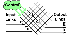
Figure 11: A Crosspoint Switch
The advantages of this type of switch are:
- the switch is very simple
- there is no blocking within the switch, although blocking may occur at the output when two input paths request the same output.
The disadvantages are:
- The number of required crosspoints is the square of the number of ports on the switch. As the switch grows in size the cost grows exponentially.
- The size of the switch can be reduced by connecting the inputs to the outputs through a set of intermediate data paths. The problem with this is that blocking can now occur within the switch because there will be fewer intermediate data paths than inputs or outputs.
- The switch is controlled by a centralised logic function. As the switch gets bigger, the rate of requests to the control element increases. This causes queuing delays and contention within the control element.
Bus/Backplane Switches
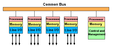
Figure 12: Bus/Backplane Switch
In a bus switch (see figure 12), external links connect to the switch via an adapter card. The adapter card is really a miniature switch in itself because it performs all the switching and routing functions. Data is transferred between adapter cards on a bus.
The advantage of the bus switch is:
- it is fast due to the high throughput of the bus, transferring data bits in parallel.
The disadvantages of this type of switch are:
- Only one adapter card can send data at a time and so the total system throughput is equal to the throughput of the bus.
- There is an overhead in the arbitration used to decide which adapter can use the bus.
- As the length of the bus increases, it gets slower and less effective. This limits the number of adapters on the bus.
Multistage Switches
The simplest form of serial stage-by-stage switching is the "Banyan" switching network (figure 13).
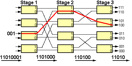
Figure 13: A Banyan Switch
The concept here is very simple:
- Each box in the switching matrix represents a single switching element, each of which has two inputs and two outputs.
- The switching elements are connected via serial (one bit at a time) link connections.
- Input and output links are considered to be quite separate although in a practical switch inputs and outputs are paired to form full-duplex connections.
When a stream of bits (block of data to be switched) arrives at an input, the switching element uses the first bit received to determine which of its two output links will be used to forward the data. The bit used to determine the routing is discarded and the block is sent onward to the next switch stage where the process is repeated. At each switch stage there is minimal buffering of the data, resulting in a synchronous switching operation from end to end. The beginning of a cell is being output from the switch before its end has been received.
The advantages of a Banyan switch are: The Banyan switch is simple, modular, expandable and uses minimal delay through it, however, it has the disadvantage that if two blocks of data passing through the switch at any time need to use a common link (switch output), then a collision occurs. This problem can be overcome by buffering the data in each switch element, causing a delay in the switch and increasing the transit delay in the network.
The PNNI Protocol
The Private Network-to-Network Interface (PNNI) protocol is used to establish, maintain and delete connections.
The ATM switch converts the input VPI (Virtual Path Identifier) and VCI (Virtual Channel Identifier) to the output VPI/VCI pairs by using an appropriate routing table. ATM switches make their routing decisions according to the contents of the routing table.
PNNI Hierarchy
Switches in an ATM network are arranged as a hierarchy of peer groups, shown in figure 14. Each switch in a group has an identical peer group identifier, which is assigned at configuration. Each switch in a peer group has an identical view of the group stored in its own topology database or routing table.
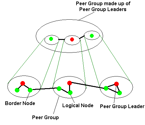
Figure 14: PNNI Hierarchy Structure
Each peer group assigns a peer group leader, which represents the peer group in the next layer of the hierarchy. In the next level of the hierarchy, the peer group leaders are arranged into peer groups. The peer group leaders give a summary of their peer group to the other members of the higher peer group and they filter down a summarised picture of the other groups to their own peer group. In this way, each switch has a detailed topological view of it's own peer group and a summarised view of the rest of the network. The switch uses this database or routing table to update the VPI and VCI fields in a cell before it leaves the switch.
The Hello protocol
When a switch is switched on, it immediately exchanges a `hello' packet, describing itself, to it's neighbours. If the neighbours have the same peer group ID, then they belong to the same peer group and they share their topological information with each other, updating their databases if necessary, so that each switch has the same view of the peer group. This is called flooding. If they have different peer group ID's they are border nodes of the peer group.
PNNI Signalling
Signalling protocols are used to set up connections. These protocols exchange information that enable calls to be established and controlled. The complex routing problem is divided into smaller problems by routing across individual peer groups.
LAN Emulation
We now know the basics of how ATM works, however, ATM is expensive to install from scratch and many users want to continue to use their ethernet LAN's, gradually transferring over to ATM as the amount of traffic increases. ATM can be used on LAN's and has a LAN emulation mode to cope with this.
LAN's operate in a connectionless environment i.e. the user sends out a packet with the destination address in the header and the packet gets there by the best route it can find. Also, packets can be marked as broadcast packets that are receive by all nodes. Broadcast packets are used to advertise what is on the network.
By contrast, ATM operates in a connection-orientated environment, which poses a problem to broadcast packets. There isn't a mechanism in ATM to send a single cell to all nodes and since a single ATM could consist of LAN and WAN connections, the broadcast message wouldn't know where to stop. To overcome these problems and allow ATM to be used in a LAN environment, LAN emulation was developed.
In a LAN environment there will be two types of user - those that have ATM cards installed and operate directly onto the ATM network and those that form an existing ethernet or token ring which route via a router onto the ATM network as illustrated in figure 15.
If there are two ethernet segments linked by an ATM network, the ATM is seen as a wide-area link which can be linked to via a bridge at either end. The bridges create a point-to-point connection between themselves. They take care of forming ATM cells from ethernet packets and rebuilding at the other end. In the case when there are more than two ethernets connected by an ATM network, the principle is the same: a particular bridge will make a point-to-point connection with a specific other bridge to transfer data.
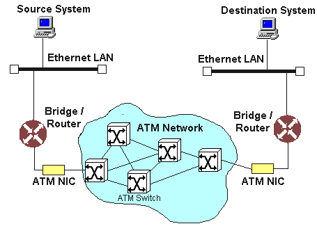
Figure 15: Ethernet to Ethernet Connection via ATM
If an ATM user want to communicate with an ethernet user, it becomes more complicated. Firstly, the ATM machine needs to understand how to divide ethernet packets into cells. Secondly, there needs to be something to translate ethernet addresses into a form understood by the ATM network and vice versa. Thirdly, there needs to be some form of broadcast capability in both directions, since the higher level protocols will expect an ethernet-like network at the lower level.
To solve these issues, the following steps are taken:
- The ATM machines run LAN emulation client software to deal with splitting up and reconstructing ethernet packets
- The higher level network protocols on ATM machines assume they are sitting on an ethernet network, although direct access to ATM features is possible
- The following services are running:
- LAN Emulation Server (LES)
This service deals with the setting up of virtual channels and the translation between ethernet addresses and ATM addresses. - LAN Emulation Configuration Server (LECS)
This service provides the configuration information, such as where to find the LAN emulation server - Broadcast and Unknown Server (BUS)
This service provides emulation of broadcasts. Broadcast packets will be directed to this server either from the bridges between the Ethernet and ATM networks or from the native ATM machines. The BUS will then re-send the broadcast packet out to all LAN emulation nodes by simply initiating a connection with each one in turn, and copying the packet. BUS can also cope with multicasts (broadcast packets with a limited subset of recipients) as well as being the recipient for any packet whose ATM address has not been resolved
- LAN Emulation Server (LES)
Summary
ATM has been developed to facilitate high speed communications of all types over long and short distances. It aims to form a single network, linking LAN and WAN.
The OSI Reference model was developed to enable subnetworks to interoperate. It consists of seven layers, covering physical connectors to network application software. Each layer performs a different task and provides a service to the layer above it. ATM sits within the second layer - data link.
ATM uses circuit switching technology to transfer small, 53 byte cells between end users. The cells don't contain a full address, since the route is pre-arranged and a virtual path set up before the cells are transmitted. The cells each contain 5 bytes of header information, including a virtual path and virtual channel identifier and 48 bytes of user data or other control data.
The quality of service is agreed when the route is set up so the end user know what service to expect from the connection. The quality of service is important when there is a mixture of voice, video, data etc on the same network because each type of traffic requires the network to behave in a different way. The quality of service defines parameters such as peak cell rate, sustained cell rate and minimum bit rate. The quality of service is set up by the ATM adaption layer (AAL).
ATM switches have to be able to cope with the very fast bit rates of ATM. The switch reads the virtual path and virtual channel identifiers of incoming cells and directs them to the appropriate output link of the switch, according to the pre-determined route. The switch updates the virtual path and channel identifiers before the cell leaves the switch. Types of switch include crosspoint, backplane and banyan. The PNNI (private network to network interface) protocol is used to establish, maintain and delete connections.
To enable ATM to be integrated into an existing LAN structure, there is a LAN emulation mode which enables the ATM part of the network to cope with LAN style packets and broadcast packets.
The future requires better, faster, more reliable communications. Present networks can't cope with the ever-increasing amount of traffic. It is becoming important for service providers to provide guaranteed network connections and quality services. ATM promises to increase network capacity and also guarantees the service between end-users on the network. Although not in common use yet, ATM is a potential solution for next generation networks.
Background Reading
Web Pages
“ATM Internetworking” by Anthony Alles, Cisco Systems, Inc., http://cell-relay.indiana.edu/cell-relay/docs/cisco.html
“Telecommunications Information” (Links to many other sites), http://www.eee.umanitoba.ca/~blight/telecom.html
“Private Network-to-Network Interface” by Mika Loukola, Helsinki University of Technology, http://www.tcm.hut.fi/Opinnot/Tik-110.551/1997/pnni/
“ATM” College of Business Administration, University of Oklahoma, http://www.busn.ucok.edu/tips/info_hrd/atm.htm
“ATM” Network World, Jan 1997, http://www.network-world.com/TECHNO/ATM_JAN.HTM
“Unravelling Asynchronous Transfer Mode” by Rawn Shah, Connectivity, Sun World On Line, April 1997, http://sunsite.uniandes.edu.co/sunworldonline/swol-04-1997/swol-04-connectivity.html
“Unravelling ATM, part two” by Rawn Shah, Connectivity, Sun World On Line, May 1997, http://sunsite.uniandes.edu.co/sunworldonline/swol-05-1997/swol-05-connectivity.html
“TCP/IP and OSI Layers”, Comp641 Enterprise Computing, http://technology.niagarac.on.ca/courses/comp641/tcpip3.htm
“Introduction ATM Switching”, by Giora Biran, http://bbs-mac.uniinc.msk.ru/tech1/1994/gbiran/atm_swit.htm
Books
“Understanding ATM” by Stanley Schatt, ISBN: 0070576793
“Handbook of LAN Technology” by Paul J. Fortier (Editor), ISBN: 0135204461
“ATM solutions for enterprise internetworking” by David Ginsburg, ISBN: 0070246793
“Asynchronous Transfer Mode Architecture and Implementation” by James Martin with Kathleen Kavanagh Chapman / Joe Leben, ISBN: 0135679184
“Enterprise Networking: Data Link Subnetworks” by James Martin with Kathleen Kavanagh Chapman / Joe Leben, ISBN: 0135075750
| Introduction | Network Traffic | Packet-Switching Technology | Local Area Network | Wide Area Network | What is ATM? | ATM & OSI | Cell Structure | Quality | Switching | PNNI | LAN Emulation | Summary | Background Reading |